KS0247 Keyestudio Pro Mini development board

Introduction:
keyestudio Pro Mini is a small microcontroller board based on the ATmega328. (datasheet), intended for use on breadboards and when space is at a premium.
It has 14 digital input/output pins (of which 6 can be used as PWM outputs), 8 analog inputs, a 16 MHz crystal oscillator, and a reset button.
Note that the board is without an on-board USB to Serial connection. To program the Pro Mini, you will need an external USB to Serial module.
The keyestudio pro mini can be powered via the pins 5V GND (DC 5V), or female headers Vin GND (DC 7-9V).
Features:
Using ATmega328P-AU from Atmel
14 digital input/output pins
8 analog input pins labeled A0 ~ A7
TTL level serial pins RX/TX;
6 PWM pins (D3, D5, D6, D9, D10, D11)
Support external DC 7-9V power supply
TECH SPECS:
Microcontroller |
ATmega328P-AU |
|---|---|
Operating Voltage |
5V |
Input Voltage (recommended) |
DC7-9V |
Digital I/O Pins |
14 (D0-D13) (of which 6 provide PWM output) |
PWM Digital I/O Pins |
6 (D3, D5, D6, D9, D10, D11) |
Analog Input Pins |
8 (A0-A7) |
DC Current per I/O Pin |
40 mA |
Flash Memory |
32 KB of which 2 KB used by bootloader |
SRAM |
2 KB |
EEPROM |
1 KB |
Clock Speed |
16 MHz |
LED_BUILTIN |
D13 |
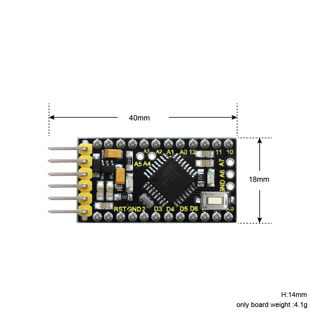
Technical Details:
Dimensions: 40mm x 18mm x 14mm
Weight: 4.1g
Element and Interfaces:
Here is an explanation of what every element and interface of the board does:
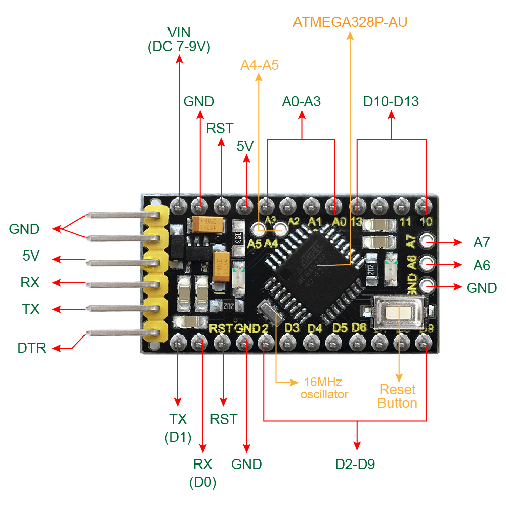

Specialized Functions of Some Pins:
Serial communication: 0 (RX) and 1 (TX). Used to receive (RX) and transmit (TX) TTL serial data.
PWM (Pulse-Width Modulation): D3, D5, D6, D9, D10, D11
External Interrupts: D2 (interrupt 0) and D3 (interrupt 1).
SPI communication: D10 (SS), D11 (MOSI), D12 (MISO), D13 (SCK).
IIC communication: A4 (SDA); A5(SCL)
Detailed Using Methods are as follows:
Step1| Download the Arduino IDE
When you get the board, first you should install the Arduino software and driver.
We usually use the Windows software Arduino 1.5.6 version. You can download it from the link below:
https://www.arduino.cc/en/Main/OldSoftwareReleases#1.5.x
Or you can browse the ARDUINO website to download the latest version from this link, https://www.arduino.cc, pop up the following interface.
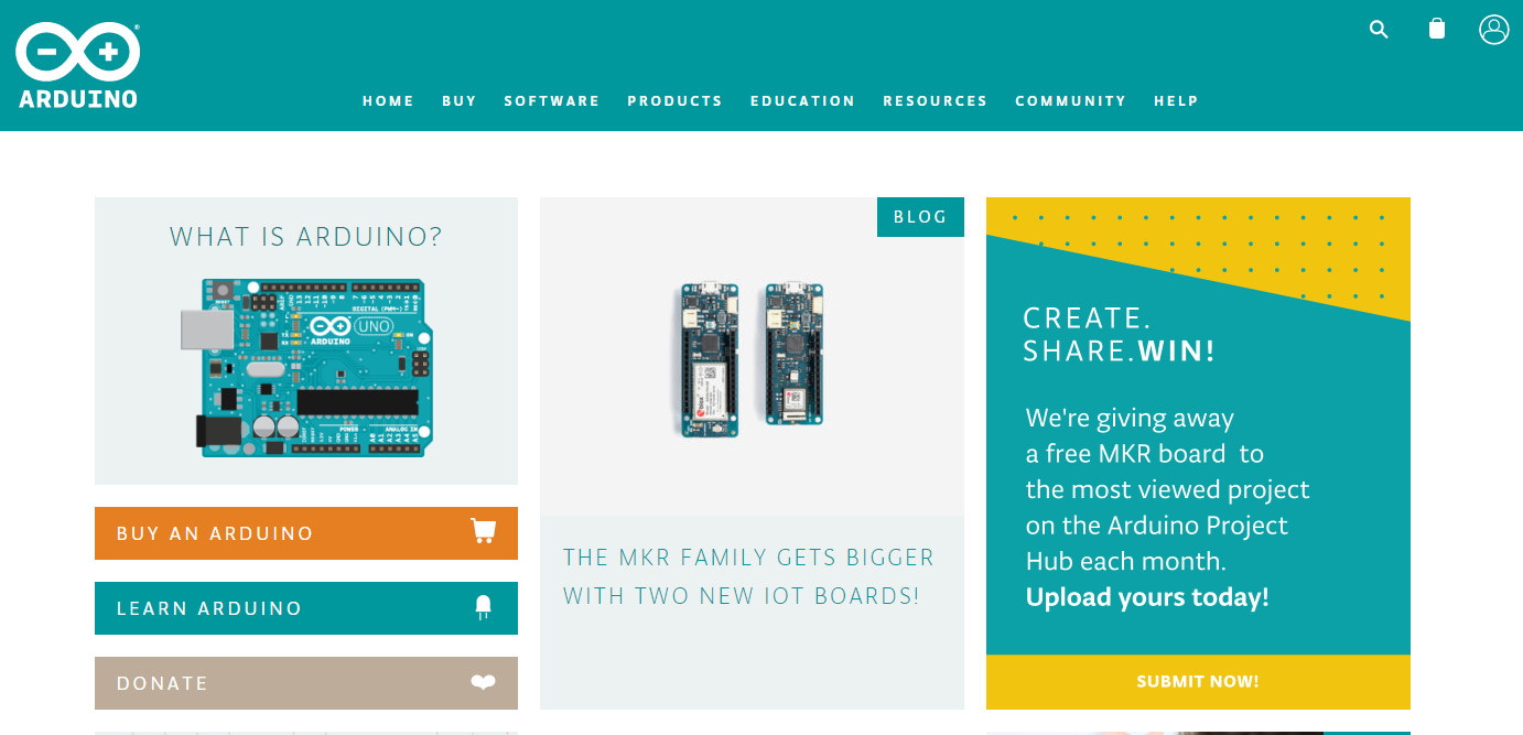
Then click the SOFTWARE on the browse bar, you will have two options ONLINE TOOLS and DOWNLOADS.
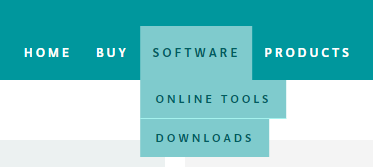
Click DOWNLOADS, it will appear the latest software version of ARDUINO 1.8.5 shown as below.
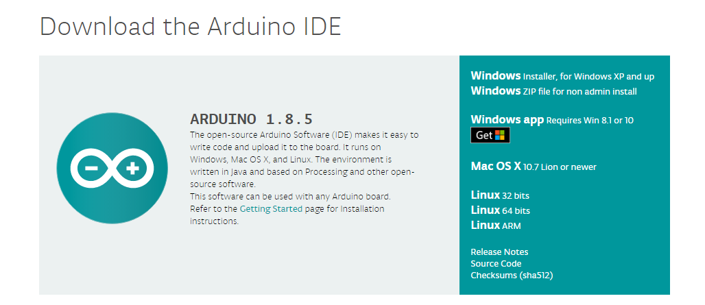
In this software page, on the right side you can see the version of development software for different operating systems. ARDUINO has a powerful compatibility. You should download the software that is compatible with the operating system of your computer.
We will take WINDOWS system as an example here. There are also two options under Windows system, one is installed version, the other is non-installed version.
For simple installed version, first click Windows Installer, you will get the following page.


This way you just need to click JUST DOWNLOAD, then click the downloaded file to install it.
For non-installed version, first click Windows ZIP file, you will also get the pop-up interface as the above figure.
Click JUST DOWNLOAD, and when the ZIP file is downloaded well to your computer, you can directly unzip the file and click the icon of ARDUINO software to start it.
Installing Arduino (Windows):
Install Arduino with the exe. Installation package downloaded well.
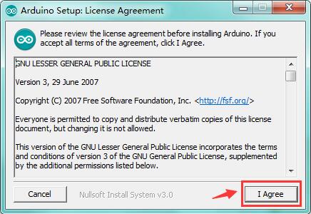
Click “I Agree” to see the following interface.
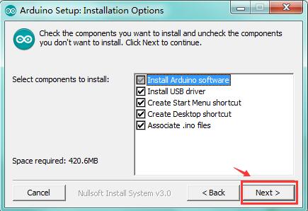
Click “Next”. Pop up the interface below.

You can press Browse… to choose an installation path or directly type in the directory you want. Then click “Install” to initiate installation.
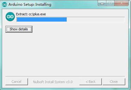
Wait for the installing process, if appear the interface of Window Security, just continue to click Install to finish the installation.

Introduction for Arduino IDE Toolbar:
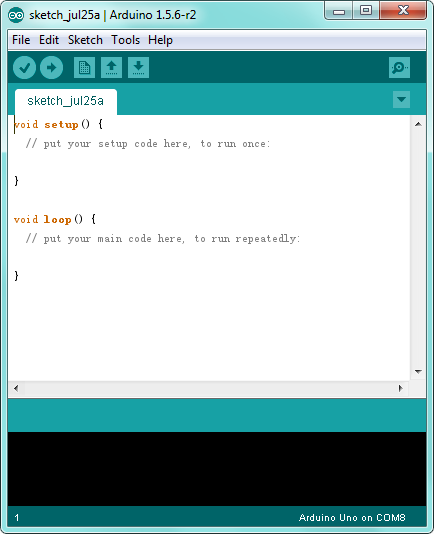
Double-click the icon of Arduino software downloaded, you will get the interface shown below.
(Note: if the Arduino software loads in the wrong language, you can change it in the preferences dialog. See the environment page for details.)
The functions of each button on the Toolbar are listed below:
http://wiki.keyestudio.com/index.php/File:IDE.png

|
Check the code for errors |
|---|---|
|
Upload the current Sketch to the Arduino |
|
Create a new blank Sketch |
|
Show a list of Sketches |
|
Save the current Sketch |
|
Display the serial data being sent from the Arduino |
 Verify/Compile
 Upload
 New
New Open
Open Save
Save Serial Monitor
Step2| Connect a USB to Serial Module
 To program the Pro Mini board,
you will need to connect an external USB to Serial module. Different USB to
Serial modules might have different driver installation. In the following, we
will introduce the use of pro mini with our keyestudio FTDI Basic Program
Downloader. See more details
here.
To program the Pro Mini board,
you will need to connect an external USB to Serial module. Different USB to
Serial modules might have different driver installation. In the following, we
will introduce the use of pro mini with our keyestudio FTDI Basic Program
Downloader. See more details
here.
Download the Driver Files

You can download the driver file from the link below:
https://drive.google.com/open?id=1vj4Is2LokXf3GDGcnumnAPmaI39uPhQk
Installing the Driver
The USB to serial port chip of this module is FT232RL. So you need to install the ft232r usb uart driver. You could click the driver file above to download it.
In different systems, the driver installation might be similar. Here we start to install the driver on the Win7 system.
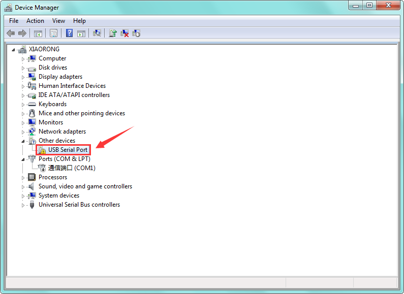
Plug one end of your USB cable into the module and the other into a USB socket on your computer.
Then right click your “Computer” —>for “Properties”—> click “Device manager”, under Other devices, you should see the “USB Serial Port”.
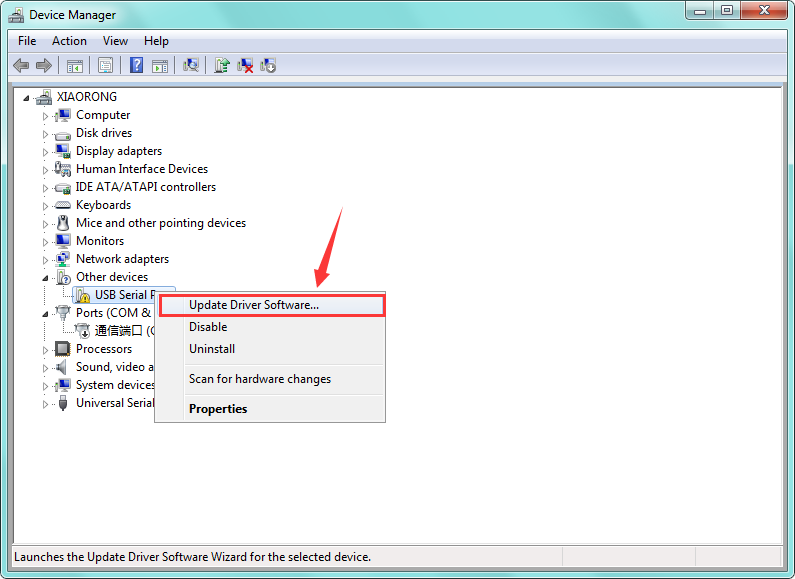
Then right-click on the USB Serial Port and select the top menu option (Update Driver Software…) shown as the figure below.
http://wiki.keyestudio.com/index.php/File:Driver_2.png
Then it will be prompted to either “Search Automatically for updated driver software” or “Browse my computer for driver software”. Shown as below. In this page, select “Browse my computer for driver software”.
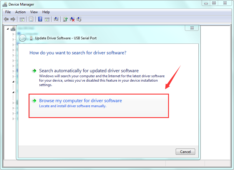
After that, select the option to browse and navigate to the “drivers” folder.

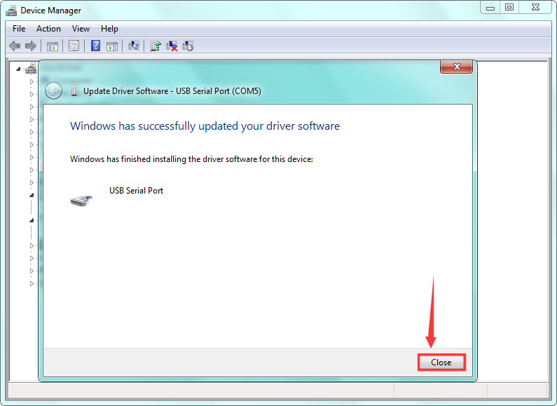
Once the driver has been installed, you will get a confirmation message. Installation completed, click “Close”. http://wiki.keyestudio.com/index.php/File:Driver_6.png
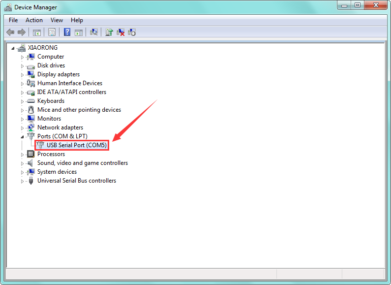
Up to now, the driver is installed well. Then you can right click “Computer” —>“Properties”—>“Device manager”, you should see the device as the figure shown below.
Step3| Hookup Guide
Driver installation completed, disconnect the module to computer, then connect it to pro mini board using F-F jumper wires. Shown below. The slide switch on the module is used to control the voltage for serial communication. Whether it is set to 5V or 3.3V, it can be programmed with the Pro Mini.

FTDI Basic Program Downloader |
keyestudio pro mini |
|---|---|
GND |
GND |
5V |
5V |
TXD |
RX |
RXD |
TX |
DIR |
DIR |
Connect well the module to pro mini board, then connect the pro mini board to your computer with a mini USB cable.
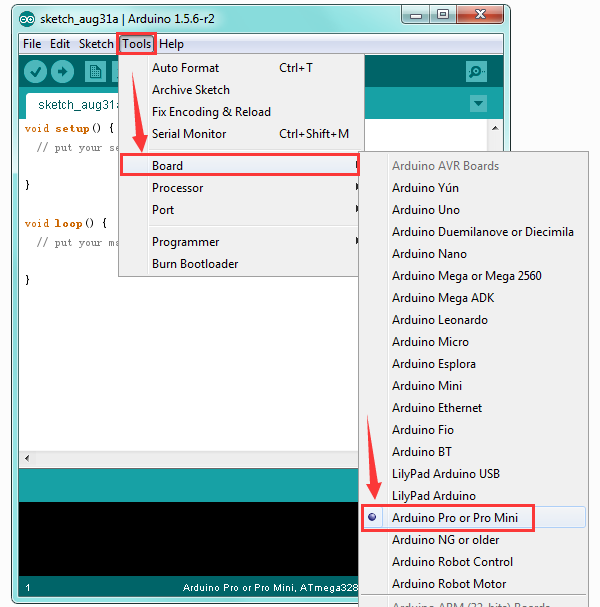
Step4| Select the Arduino Board
Open the Arduino IDE, you’ll need to click the “Tools”, then select the Board that corresponds to your Arduino.

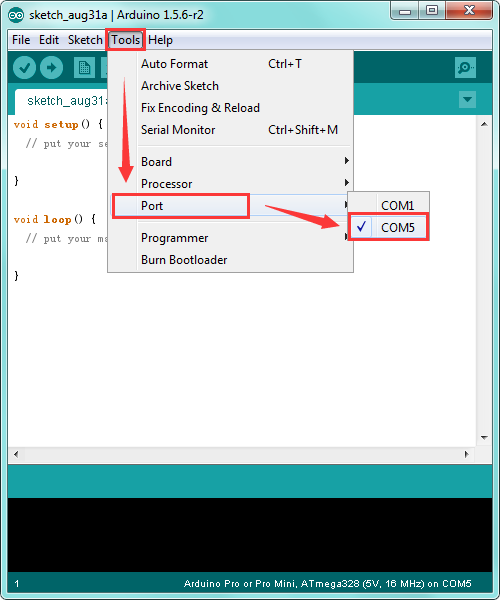
Step5| Select your serial port
Select the serial device of the Arduino board from the Tools | Serial Port menu. Note: to avoid errors, the COM Port should keep the same as the Ports shown on Device Manager.
Step6| Upload the Code
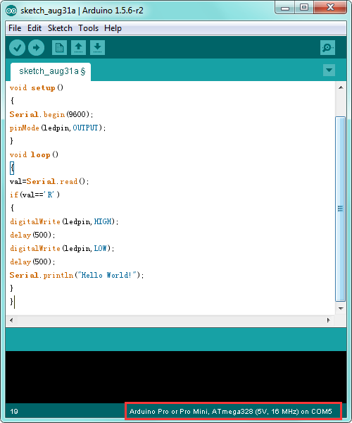
Below is an example code for displaying the Hello World!
Copy and paste the code to the Arduino environment IDE.
///////////////////////////////////////////////////////////////////////////////////////////////
int val;
int ledpin=13;
void setup()
{
Serial.begin(9600);
pinMode(ledpin,OUTPUT);
}
void loop()
{
val=Serial.read();
if(val==’R’)
{
digitalWrite(ledpin,HIGH);
delay(500);
digitalWrite(ledpin,LOW);
delay(500);
Serial.println(“Hello World!”);
}
}
///////////////////////////////////////////////////////////////////////////////////////////////
Then click verify button to check the errors. If compiling successfully, the message “Done compiling.” will appear in the status bar.

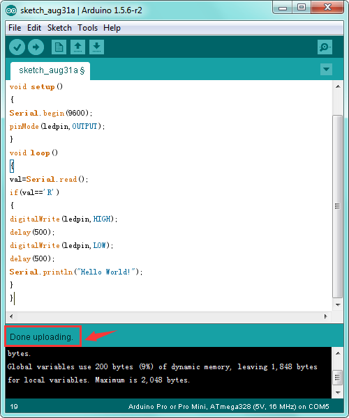
After that, click the “Upload” button to upload the code. If the upload is successful, the message “Done uploading.” will appear in the status bar.
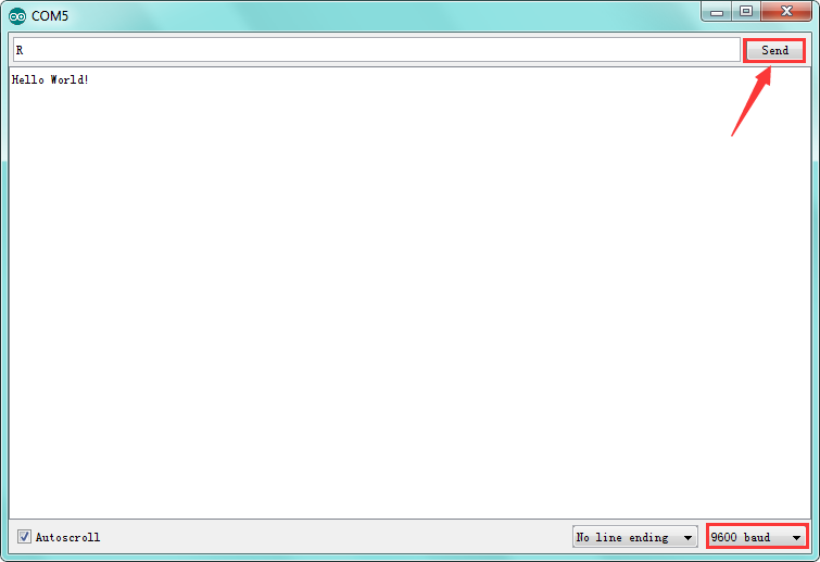
Step7| Open the Serial Monitor
After that, click the button to open the serial monitor.
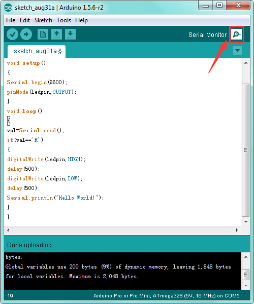
Then set the baud rate to 9600, enter an “R” and click Send, that is, the computer will send the character R. When pro mini board receives it, you should see the D13 led flash once. “Hello World!” is sent to the computer, so that you should see the “Hello World!” is showed on the monitor.
Resource Links:
Download code and libraries:
https://fs.keyestudio.com/KS0247
You might also want to look at:
the reference for the Arduino language;
Download ARDUINO Software:
https://www.arduino.cc/en/Main/OldSoftwareReleases#1.5.x
Troubleshooting:
If you have problems, please see the troubleshooting suggestions.